
 |
|
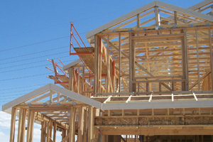
Figure 1. House using wood trusses during framing stage of construction. Photo courtesy of William Bolduc. |
Wood roof trusses are the norm for residential construction in most areas of the United States (see Figure 1). Wood trusses are also commonly used in retail, offices, commercial buildings, churches and many other low-rise buildings.
References in the Building Code
The 2006 and 2009 versions of the International Building Code (IBC) have each added more information on how wood trusses are to be submitted to building departments for plan review and inspection. The building code has added new terms like “Truss Submittal Package,” “Truss Design Drawings,” and “Truss Placement Diagram” (see "New Terms" sidebar).
Both of the newest versions of the IBC reference a corresponding version of the American National Standard: ANSI/TPI 1, National Design Standard for Metal-Plate- Connected Wood Truss Construction. The 2006 IBC references ANSI/TPI 1-2002. The 2009 IBC references ANSI/TPI 1-2007. Although some information about metal-plate-connected wood trusses is included in the IBC, ANSI/TPI 1 is needed for most of the details.
The 2006 IBC Section 2303.4.2 states that the requirements of the ANSI/TPI 1 must be met in addition to the requirements stated in the IBC.
What’s New in the Building Code?
The 2006 IBC introduced significant changes through revisions to Table 1607.1 Minimum Uniformly Distributed Live Loads and Minimum Concentrated Live Loads. Two major loading changes commonly affect the design of roof trusses.
One change is the new requirements for live loads for attic spaces in residential construction. The new code requires that any area of the roof where a rectangular prism 42-inches high and 24-inches wide can fit above the bottom chord without infringement from the top chord or web members for two adjacent trusses must be designed for 20-psf live load on that area of the bottom chord. All other areas of the bottom chord should be designed for a 10-psf live load that is non-concurrent with other live loads. In addition, the dead load should be at least 10 psf on the bottom chord. The exception is if the bottom chord pitch is 2:12 or greater.
 |
|
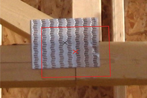
Figure 2. Plate misplacement at bottom chord joint splice. The red outline shows location specified on the truss design drawing. Photo courtesy of William Bolduc. |
What’s New in the ANSI/TPI 1 Standard?
The biggest changes in the ANSI/TPI 1 standard are new methods and procedures for quality control of the metal-plate connection to the wood members. The truss is held together by metal plates that have teeth embedded into the wood members. The strength of the truss is affected significantly by the quality of:
the position of the placement of the metal-connecter plate on the joint
the embedment of the teeth into the wood
the quality of the lumber at the contact area under the metal-connector plate.
Poor quality in any of the following will reduce the strength of the connection:
If the plate is positioned differently from what is specified on the truss design drawings, one or more of the members in the joint will have less teeth and less strength than intended by the truss design drawing (see Figure 2).
If there is a small gap (the embedment gap) between the metal plate and the wood surface, the strength of the connection is reduced. The standard allows a gap up to 1/32 inches before one must consider some reduction in capacity (see Table 1 below). If any teeth are fattened (not embedded perpendicular to the wood surface) the capacity is reduced.
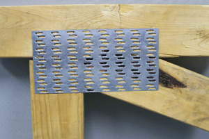
If a lumber characteristic such as a knot, wane, or pitch pocket is under the plate contact area, the strength of the connection is reduced (see Figures 3 and 4 on next page). This can occur even if the lumber is the correct grade specified on the truss design drawing. For example, No. 2 grade of structural light framing lumber typically allows wane to be up to one half the width of the board for up to one fourth the length of the board. Although this is acceptable for many structural uses, it would usually be unacceptable for one half of a board width under the plate contact area to be into wane.
The ANSI/TPI 1-2002 introduced a new factor and new quality control procedures to better account for the possibility of these factors affecting the strength of metal-plate-connected wood trusses. The ANSI/TPI 1-2007 further clarifies and refines how to use the new factor and quality procedures. Each truss manufacturer must now establish “fabrication tolerances” and have the truss design drawings engineered to match the fabrication tolerance used in manufacturing of the trusses.
| Tooth Embedment Gap, G |
G=0" | 0"<G≤1/32" | 1/32"<G≤1/16" | 1/16"<G≤3/32" | G>3/32" |
| Tooth Effectiveness |
119% | 100% | 60% | 40% | 0% |
| Table 1. Tooth Effectiveness with Various Embedment Gaps | |||||
For example, if the truss manufacturer establishes the fabrication tolerance at 20 percent, the truss design drawing will reduce the strength of the metal plate gripping design value by 20 percent. This will result in some connector plates becoming larger to account for the reduction in plate gripping values. Experience has shown that a 20 percent fabrication tolerance does not increase all plate sizes by 20 percent. Other requirements control many plate sizes. Some plate sizes on some joists do not change at all.
The ANSI/TPI 1-2002 and ANSI/TPI 1-2007 applies the fabrication tolerance as part of the in-plant quality procedures. If the fabrication tolerance is set to 20 percent, up to 20 percent of the plate contact area may be affected by the strength-reducing issues previously discussed and still be acceptable. This provides a more streamlined quality process with a clear and measurable criterion. If a building inspector sees a joint that is not perfect, knowing the fabrication tolerance helps to determine if the issue is serious.
 |
|
Figure 3. Pitch pocket under plate area. Pitch is the tree sap (liquid or dried) that can fill voids between the growth rings in wood. Photo courtesy of William Bolduc. |
If the big change is related to in-plant quality control, it may seem irrelevant to the truss submittal process for plan examination and inspection. In fact, the fabrication tolerance affects the plate sizes and one must state it on the truss design drawings submitted for plan examination and inspection. There is a simple method to discover if the truss manufacturer is following the new building codes. Ask the question, “What is the fabrication tolerance?” It should be stated on every truss design drawing that is submitted.
It may be clearly stated on the truss design drawing as the fabrication tolerance or indirectly stated as the quality control factor, Cq. ANSI introduced the quality control factor, Cq, in ANSI/TPI 1-2002. The meaning of the quality control factor was changed in ANSI/TPI 1-2007. In both cases, there is a direct correspondence between the fabrication tolerance and the quality control factor, Cq (see Table 2 below). ANSI/TPI 1 states that either the fabrication tolerance or the quality control factor, Cq, must be stated on each truss design drawing. For better clarity, the newer version (2007) of the standard requires that the fabrication tolerance be stated on each truss design drawing.
| Fabrication Tolerance |
Quality Control Factor, Cq | |
| Per ANSI/TPI 1-2002 | Per ANSI/TPI 1-2007 | |
| 0% | 1.25 | 1.00 |
| 10% | 1.125 | 0.90 |
| 11% | 1.11 | 0.89 |
| 20% | 1.00 | 0.80 |
| 30% | 0.875 | 0.70 |
| Table 2. Equivalent Quality Control Factor for Various Fabrication Tolerances | ||
If you do not see the fabrication tolerance or the quality control factor, Cq, on the truss design drawings, that may indicate that the truss manufacturer is not following the current codes and standards and/or the third-party agency that is required to monitor the in-plant quality procedures is not following the current standards. In either case, your question of “What’s your fabrication tolerance?” will likely encourage the truss manufacturer to improve quality and follow the building codes and standards.
 |
|
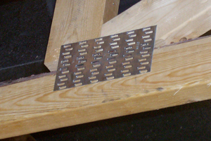
Figure 4. Wane under plate contact area of bottom chord. Wane refers to the lack of wood or bark on the edge or corner of lumber. Photo courtesy of William Bolduc. |
There is no single correct value. It depends on the quality control procedures used by the truss manufacturer. The fabrication tolerance may be any value from zero to 30 percent (or even higher). What is important is that the fabrication tolerance shown on the truss design drawings match (or exceed) the fabrication tolerance used by the truss manufacturer for their quality control procedures. The third-party agency that audits the quality control procedures used in the truss plant must also agree that the quality procedure matches the fabrication tolerances shown on the truss design drawings.
Typically, truss manufacturers will use a higher tolerance for roof trusses (plates embedded into the wide face of the lumber) than for floor trusses (with plates embedded into the narrow edge of the lumber). This is due to the greater geometric complexity of roof trusses and the manufacturing process that may require placement of a truss plate on the underside of the connection for roof trusses.
If the fabrication tolerance is less than 20 percent for roof trusses (plates into wide face) or 11 percent for floor trusses (plates into narrow edge), the ANSI/TPI 1-2002 (Section 3.2.4.2) requires that the truss manufacturer provide to the approved inspection agency, or through other means, “justification” for the lower fabrication tolerance. ANSI/TPI 1-2007 does not have this requirement (see Table 2 for conversion of the fabrication tolerance to the quality control factor, Cq, value).
Conclusion
The new versions of the building codes and standards have significantly improved and clarified the requirements for Metal-Plate-Connected Wood Truss Construction. Truss designers and manufacturers, third-party quality agencies, plan examiners, and building inspectors need to adopt and follow these new changes.
William Bolduc, P.E., S.E. is a structural engineer with the A.C. Houston Lumber Company. He is an expert on several aspects of wood-frame construction. He is a Professional Engineer in 27 states and a Structural Engineer in Nevada, Utah and Texas. Bolduc has a bachelor’s degree in Civil Engineering from the Illinois Institute of Technology and a master’s degree in Civil Engineering from the University of Nevada Las Vegas.